
Are You Making These Common Precision Machining Mistakes?
- helvinbacareza

- Dec 24, 2025
- 4 min read
Precision aerospace components demand tolerances measured in microns. A single machining error can compromise mission-critical systems and result in costly part rejection. Manufacturing teams across the aerospace industry continue to encounter recurring technical challenges that impact precision aerospace components production.
Tool Deflection: The Silent Precision Killer
Tool deflection represents the most significant threat to precision aerospace manufacturing processes. Excessive cutting forces cause tool bending, particularly during deep cavity machining operations common in aerospace components.
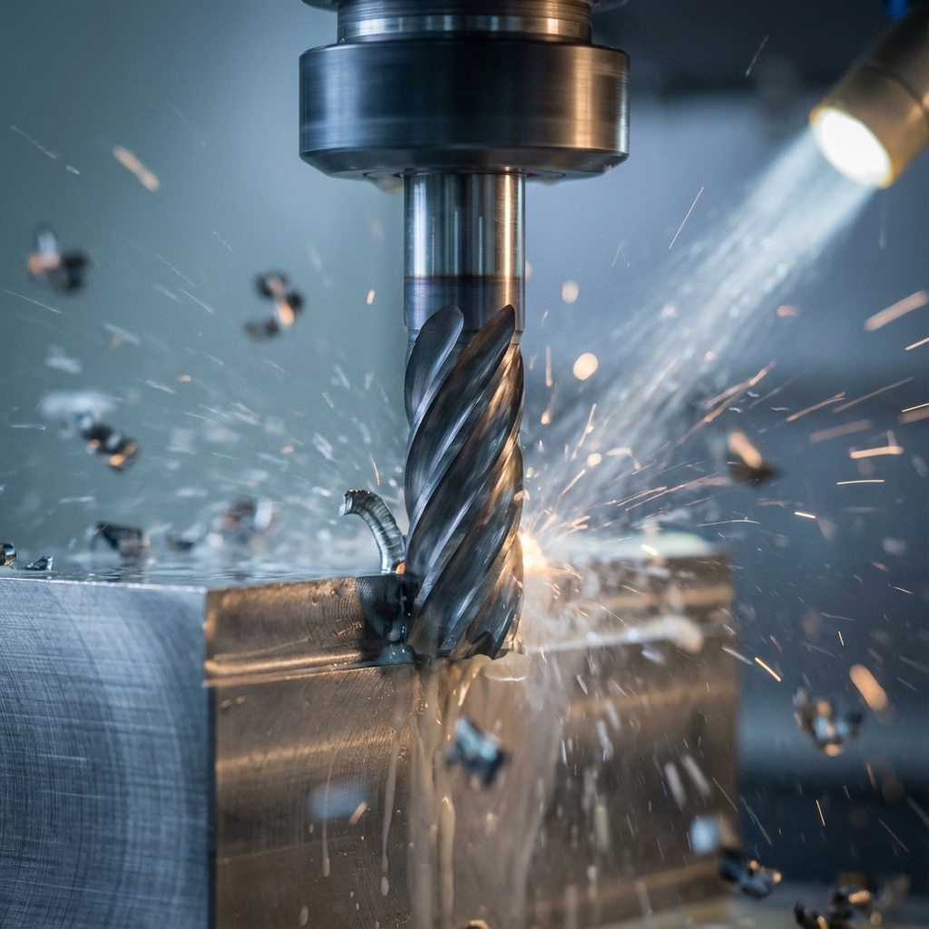
Long, slender tools deflect under cutting loads, creating dimensional variations across machined surfaces. This deflection increases proportionally with tool length and cutting forces. Aerospace manufacturing processes require tool selection based on length-to-diameter ratios below 3:1 for critical operations.
Carbide tools with enhanced rigidity specifications minimize deflection compared to high-speed steel alternatives. Tool path strategies must account for deflection compensation through adaptive cutting parameters. Programming shallow depths of cut with higher feed rates reduces cutting forces while maintaining material removal rates.
Setup rigidity directly impacts tool deflection characteristics. Machine spindle bearings, workholding fixtures, and tool holder assemblies must provide maximum stiffness. Any compliance in the machining system amplifies tool deflection effects.
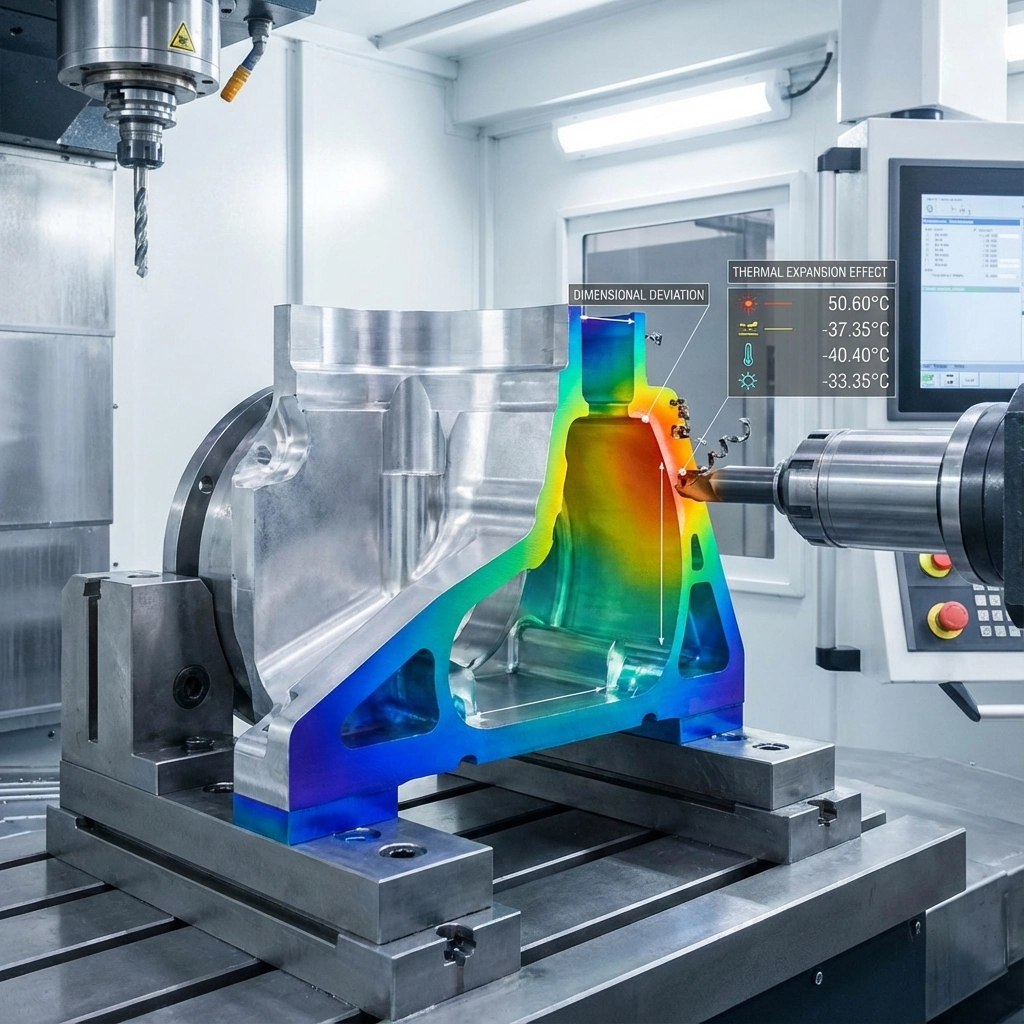
Thermal Expansion: Temperature-Induced Tolerance Violations
Thermal expansion affects both workpieces and machine tools during aerospace machining operations. Temperature variations of 1°C can cause dimensional changes exceeding aerospace component tolerances.
Machine thermal stability requires controlled ambient temperatures and spindle warming protocols. Extended machining cycles generate heat through cutting processes and friction. This heat transfers to workpieces and machine structures, causing dimensional drift.
Coolant systems must maintain consistent temperatures throughout production runs. Flood coolant application provides superior heat removal compared to mist cooling for precision aerospace components. Through-tool coolant delivery directly targets cutting zones where heat generation occurs.
Workpiece thermal expansion becomes critical during long machining cycles. Aluminum aerospace components expand significantly more than steel or titanium alternatives. Fixture design must accommodate thermal growth while maintaining part location accuracy.
Temperature monitoring systems track workpiece and machine temperatures throughout production cycles. Compensation algorithms adjust tool paths based on thermal measurements. This approach maintains dimensional accuracy despite temperature variations.
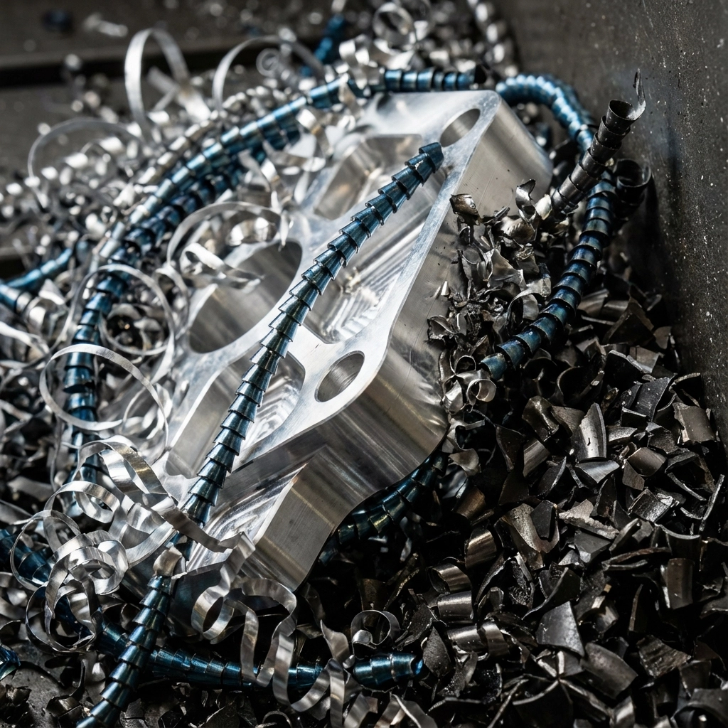
Chip Management: Controlling Secondary Cutting Operations
Improper chip management creates secondary cutting conditions that degrade surface finishes and dimensional accuracy. Chips that remain in cutting zones cause scratching, work hardening, and tool damage.
Aerospace manufacturing processes generate various chip types depending on material properties and cutting parameters. Aluminum alloys produce long, continuous chips that wrap around cutting tools. Titanium creates segmented chips with sharp edges that damage machined surfaces.
Chip evacuation systems must remove chips immediately from cutting zones. High-pressure coolant streams transport chips away from workpieces. Chip conveyor systems prevent chip accumulation in machine work areas.
Tool geometry selection influences chip formation characteristics. Positive rake angles reduce cutting forces and promote chip breaking for improved evacuation. Chip breaker geometries control chip size and shape for specific materials.
Programming considerations include dwell time elimination and continuous tool motion to prevent chip packing. Ramping strategies avoid plunge cutting operations that trap chips in cavities.
Setup Rigidity: Foundation for Precision Aerospace Manufacturing
Setup rigidity determines machining system capability for precision aerospace components. Insufficient rigidity causes vibration, chatter, and dimensional inaccuracy during cutting operations.
Workholding systems must provide maximum clamping force without workpiece distortion. Soft jaw fixtures distribute clamping loads across larger contact areas. Hydraulic clamping systems maintain consistent clamping force throughout temperature cycles.
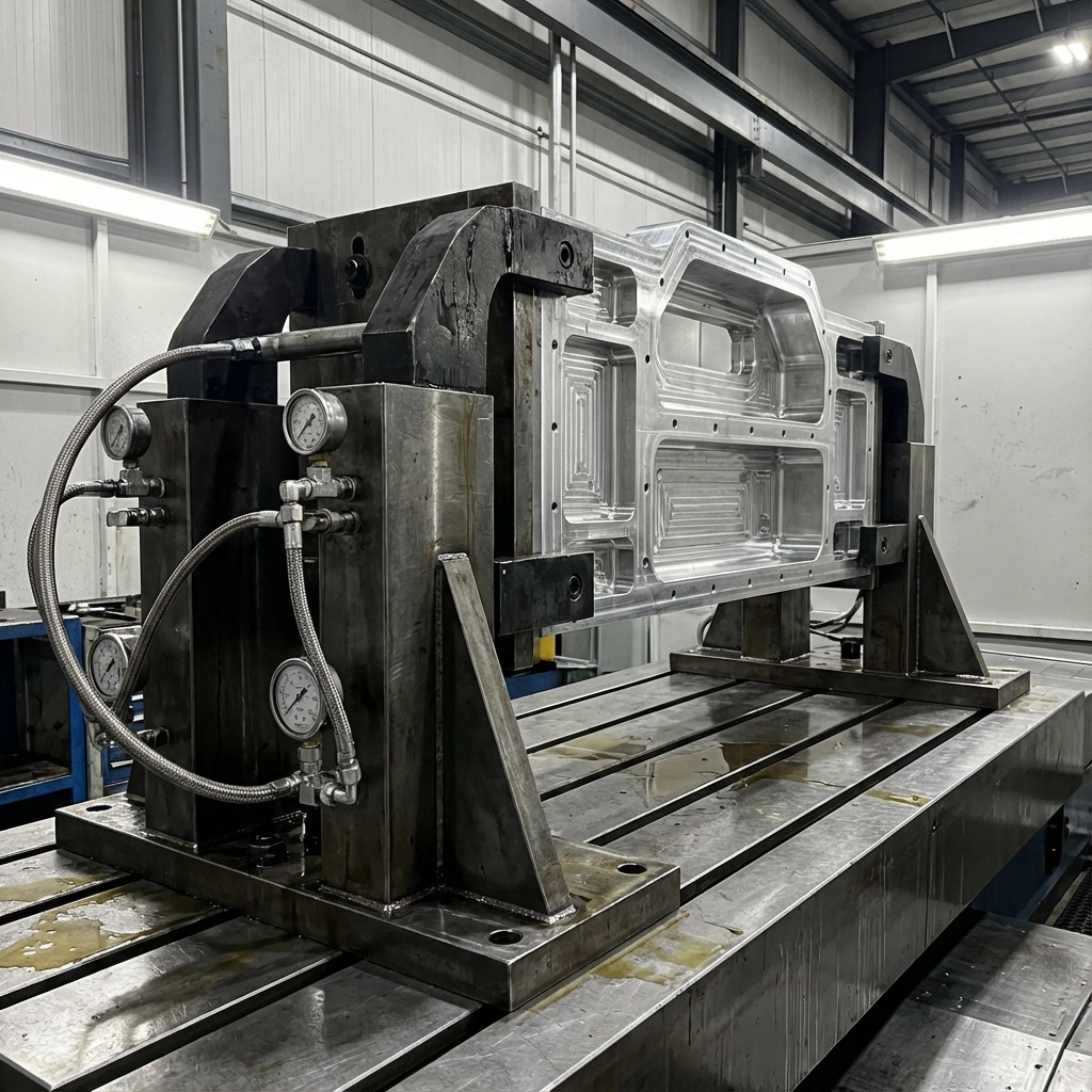
Fixture design requires adequate mass and stiffness to resist cutting forces. Steel fixtures provide superior rigidity compared to aluminum alternatives. Fixture mounting bolts must achieve specified torque values to eliminate compliance.
Machine tool condition directly affects setup rigidity. Spindle bearing wear creates runout and vibration issues. Way wear allows machine axis movement under cutting loads. Preventive maintenance programs maintain machine rigidity specifications.
Cutting parameter selection must account for setup rigidity limitations. Lower cutting speeds and feed rates reduce dynamic forces that excite system resonances. Progressive roughing strategies remove material gradually to minimize cutting forces.
Tool Selection Errors in Aerospace Applications
Incorrect tool selection remains a primary source of precision machining failures in aerospace manufacturing processes. Tool specifications must match material properties and machining requirements for precision aerospace components.
Carbide grade selection affects tool performance and part quality. Uncoated carbide tools work effectively for aluminum aerospace components but fail rapidly in titanium applications. PVD coatings extend tool life while maintaining sharp cutting edges required for precision work.
Tool geometry parameters including helix angle, rake angle, and edge preparation must suit specific aerospace materials. Sharp cutting edges minimize work hardening in titanium alloys. Polished cutting edges reduce adhesion in aluminum machining operations.
End mill diameter selection impacts tool deflection and surface finish quality. Larger diameter tools provide increased rigidity but may not access tight geometries common in aerospace components. Tool length must remain minimal while providing necessary reach.
Measurement and Quality Control Deficiencies
Measurement accuracy determines conformance to aerospace component specifications. Improper measurement techniques generate false readings that lead to part rejection or acceptance of non-conforming components.
Coordinate measuring machine (CMM) setup requires proper workpiece fixturing and temperature stabilization. Measurement uncertainty must remain below 10% of the tolerance being verified. Probe qualification verifies measurement system accuracy.
Surface finish measurement requires appropriate instrumentation and technique. Ra values specified for aerospace components demand calibrated surface roughness measurement systems. Measurement location selection affects reported surface finish values.
Dimensional measurement during machining operations provides process control feedback. In-process probing systems verify dimensions without part removal from fixtures. This approach maintains setup accuracy and reduces cycle times.
Process Control and Documentation Requirements
Aerospace manufacturing processes require comprehensive process control and documentation systems. Statistical process control (SPC) monitors machining processes for trend identification and corrective action implementation.
Tool life monitoring prevents tool failure during critical machining operations. Tool wear measurement systems track cutting edge condition and predict replacement timing. This approach prevents unexpected tool failure and associated part damage.
First article inspection procedures verify process capability before production implementation. These inspections identify potential issues before full production runs commence. Documentation requirements include setup sheets, tool lists, and inspection reports.
Process parameters including cutting speeds, feed rates, and tool paths require documentation and control. Parameter changes demand engineering approval and process validation. This approach ensures consistent part quality throughout production runs.
Manufacturing teams that address these technical challenges achieve superior precision aerospace component quality. Systematic approach to tool deflection, thermal management, chip control, and setup rigidity provides the foundation for successful aerospace manufacturing processes.
Comments